Installing the SW-Motech Evo Quick-Release Rack on a 2009 Suzuki DL650 V-Strom
Disclaimer: I am not a mechanic. I build computer networks for a living. Therefore, I am not qualified to tell you that anything I have posted here is the right way to do things on your motorcycle. These instructions are offered in the hope that they might show someone considering the SW-Motech Evo racks the work involved in installing them on an '09 V-Strom. The instructions *may* work on other year DL650's and *may* work on the DL1000 V-Stroms as well, but I don't have access to these bikes. You *MUST* use your own judgment when working on your motorcycle. If you break your bike following these instructions, I accept no liability since I am admitting up front that I do not know what I am talking about!
Still here? Good! If I haven't scared you off yet, let's get started :)
This first picture is the starting point. I have layed out all of the parts including in the SW-Motech kit (besides the Lock-tite -- you have to provide that yourself) on the table. I highly recommend you do likewise. A clean, organized workspace will make the job a lot easier and a lot more fun.
The first step is to remove the four bolts -- the four bolts that I have loosened in this photo -- that hold the factory luggage rack on the motorcycle. Use a 10mm socket to remove these bolts, then lift the luggage rack off the bike.

Next, you have to remove the rear fender. This is the point where I stopped when I first received the racks, because I thought there had to be a better way. There wasn't, at least that I could find, and it really wasn't nearly as ard as I first thought it would be. Just remove these two screws...
...and pull up and back on the fender. You will see four round cut-outs in the fender -- two for two of the four bolts that attach the luggage rack and two for the two screws that hold the fender onto the motorcycle -- and underneath the fender, there are little plastic rings that protrude through the fender. If you pull and wiggle the fender, it will rise up over these plastic rings, and the fender will pop off the bike.

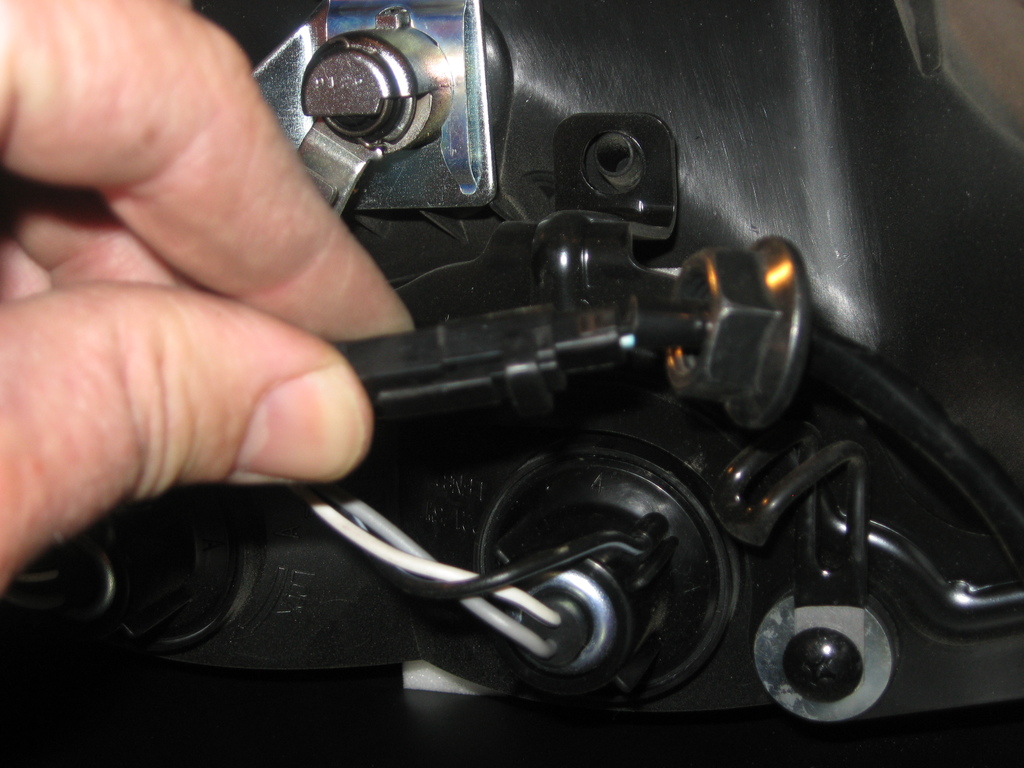
Now, remove the seat release cable. The cable ball end fits in a circular housing that you can see near the middle of this photo. Pull the housing towards the cable (to get a little slack in the cable), rotate the cable towards the cutout that you can see at the four-o-clock position on the housing, then lift the ball end out of the housing. Lift up on the cable where the cable sheath snaps into the plastic frame (just left of center in the photo. It's just pressed into place, so it will just snap loose when you pull on it hard enough. The cable should now be free of the motorcycle. If you want, you can disconnect the wire harness quick-connect between the motorcycle and the tail lights and turn signals, but I didn't find it necessary. I was able to lay the fender on the under-seat storage to do all the work. If it makes your life easier, release the disconnect. If not, you can leave it attached.

 |
| This was the scariest part of the install...no turning back now! |

Next, it is time to remove the turn signals. The first photo shows the nut (on the left-hand side of the photo) that holds the turn signals to the fender. Use a 17mm wrench to remove the nut. The second photo shows the quick disconnect for the wires to the turn signal. The turn signal wiring will have the
black quick disconnects, and the tail light wiring will have the
white quick disconnects. Cut the wires on either side of the quick disconnects (make SURE you cut the wires for the turn signals *ONLY*!!!) Once you've cut the wires, slip the nut off the wiring, and remove the turn signals from the fender.

Now, remove the license plate bracket from the rear fender. The SW-Motech kit replaces the stock license plate bracket with a much stiffer bracket (shown in the second photo) to hold the racks, so you will be discarding the OEM part. There are two nuts inside the fender that hold the OEM bracket to the fender. Use a 10mm socket to remove them...
...then replace the OEM bracket and hardware with the parts supplied in the SW-Motech kit. Make sure the SW-Motech bracket is approximately centered on the fender before tightening the nuts down! [b]Note:[/b] The SW-Motech instructions say to drill two new holes in your license plate to attach it to the bracket with the same hardware that attaches the bracket to the fender. You can do this, but I opted to...
...drill two more holes in the fender at the outer reach of the slots machined in the SW-Motech bracket and use the original mounting holes in my license plate. This way, if I ever want to remove the license plate, I don't have to remove the entire bracket to do so. You probably should put spacers between the plate and the SW-Motech bracket under the bolts that attach the plate, since the bolts that hold the bracket to the fender will lift up the center of your license plate! (see the third photo to see what I mean)


Unfortunately, the SW-Motech kit requires you to relocate your turn signals. Fortunately, they include brackets to let you do this (shown in the first photo). I got creative at this point. The astute observer will notice that in the second photo, there is another hole in the brackets that isn't shown in the first photo. I decided to route the turn signal wiring through the hole that was used to align the turn signals in their original mounting location. In hindsight, I probably wouldn't do this again -- you end up making some rather sharp-radius bends with the wiring, which I suspect may lead to early failure of the turn signal wiring. I think it would probably be better to drill a new hole in the fender (use a rubber grommet to keep the fender from vibrating through the insulation on your wires!!!) and route the wiring through there.


Use the new hardware supplied by SW-Motech to attach the turn signal brackets to the fender (the bolt uses an 8mm allen wrench, I believe, and the nut requires a huge 19mm wrench or socket), then attach the turn signals to the bracket. Two things to notice here: 1) the bracket bends *upwards* when installed on the fender, and 2) make sure you attach the right turn signal to the right side of the fender and the left turn signal to the left side of the fender. They will fit on either side, but it's easier to match up the wiring if you attach the appropriate turn signal to the appropriate side (IIRC, the right side turn signal has one blue wire and one black wire with a white stripe, whereas the left side is one black wire and one black wire with a white stripe). Yes, I initially put them on the wrong side. Yes, I was neurotic enough to swap them :)


Once the turn signals are relocated, the stock wiring isn't long enough to reach. SW-Motech includes additional wire for the turn signals. The SW-Motech kit does not include heat shrink tubing to cover the butt splices (in blue, in the photo), and it's probably not necessary. However, I had some laying around (in dark grey), so I cut a few lengths of heat shrink tubing that was longer than the butt splices I used to reattach the turn signal wiring.
These metal tabs will fit over the passenger footrests and are used to attach the luggage racks to the bike. Notice the angle in the tab, and make sure you insert the bolt through the correct side (!) and slip a spacer over the bolt.
IMPORTANT NOTE! At this point, only tighten the bolts on the mounting tabs enough to hold them in place -- do not lock them down until you have fit the luggage racks on the mounting tabs!
Use an allen wrench to remove this one bolt from the passenger footpegs on the right side of the bike...
...and replace that bolt with the tab assembly. The spacer fits into the recess in the footpeg mount. Once again, don't tighten it all the way yet!
Next, replace the fender on the rear of the motorcycle, then place the two aluminum spacers in the holes where the bolts attach the cargo rack to the fender. The aluminum spacers are smaller on the bottom than they are on the top, so make sure you orient them correctly. The spacer on the left is already in place; the spacer on the right is upside down to show the smaller underside.
In this photo, the factory cargo tray is shown upside down on the fender, with the mounting tab for the rear of the Quick Carrier shown in place on the cargo tray. Notice how the mounting tab bends upwards in this photo? That's important -- when the tab and the cargo tray is installed on the bike, the tabs should angle
downwards.
Here is how the rear mounting tabs should look when the cargo tray is installed on the bike, as seen from the rear...
...and from the top. Notice that I haven't tightened these bolts down yet!
Now, install these mounting tabs under the passenger grab rails. You guessed it -- leave them loose for now!
Now, to install the mounting tab at the left side passenger footpeg.
The procedure is similar to the left hand side, but the left side tab is a little longer since the passenger footpegs are not quite symmetrical. Make sure you use the correct tab for the correct side!
Here's a photo with the left side mounting tab in place. Notice that the left tab is
under the passenger footpeg mount, while the right side was
over it. And no, I
still haven't locked the mounting tabs down, yet.
Once I had all the mounting tabs installed, I found these odd little washers left in my hardware tray. At first, I wasn't quite sure what they were...
...but then I figured it out. These washers fit over the cam-lock screws to keep them from falling out of the luggage rack when you remove it from the bike. I found out the hard way that you do
NOT want to test fit the washers on the cam-lock screws until you have already inserted them in the luggage rack! They are a snap (literally) to install, but a real bear to remove.
Here's a shot of the installed luggage rack on the right side.
Here's a shot of the left side.
And one from the rear. Now that the racks are in place, go ahead and tighten up all of the bolts on the mounting racks. If you tighten them before this point, it will be impossible to adjust the mounting tabs into the proper position to install the luggage racks, unless you are incredibly lucky and got it right without fitting the racks :)
I used some square aluminum tubing to rig up spacers so I could install a set of Pelican 1430 boxes to the luggage racks. This procedure is outside the scope of this blog entry, but I might do another entry in the future describing how I did it.
The 1430s are probably a little small if you want to use your V-Strom for any real touring, but for commuting around town, they are great. You would not believe how much groceries I can fit inside these little boxes, LOL!


 How about now? Yep, that's it. That tiny little scratch was all the damage there was. As I said over at Stromtrooper, consider it "factory distressed." :)