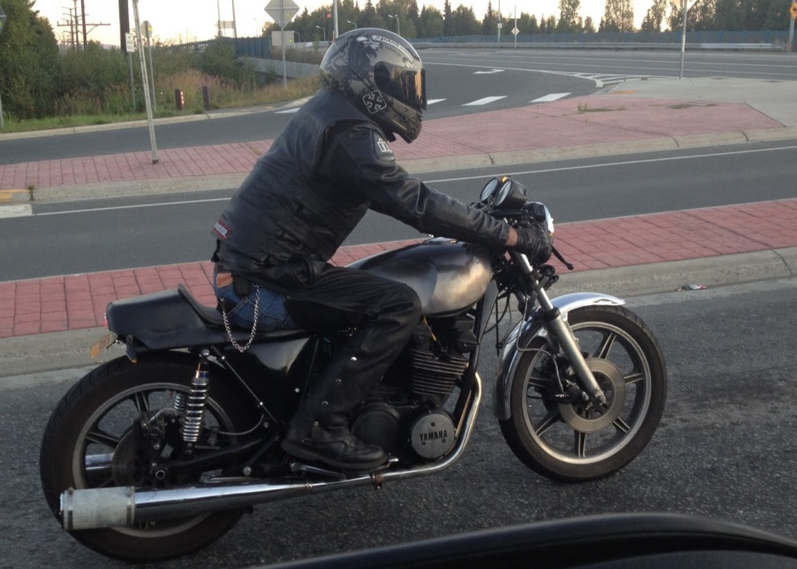
Showing posts with label project bike. Show all posts

Sunday, June 24, 2018

GL1000 -- Steering Head Bearings

"I have not failed. I have merely found 10,000 ways that do not work." --Thomas Edison

Before wrapping up the GL1000 project for the "winter" (now that it's the middle of June), I needed to replace the steering head bearings. During my ride to Whittier for a cup of coffee (lol) last Father's Day, I noticed that the steering on the bike felt a little notchy. Since I don't know the service history of the bike -- in fact, I don't even know its total mileage -- I decided that I should probably replace the steering head bearings after the riding season ended, which was probably a wise decision. Waiting until the next riding season before starting...that, perhaps, was not quite so wise ;)

In theory, this should be a pretty simple task. It's a lot of steps, but each task is pretty straightforward. Nothing too difficult, right?

Well...yeah, that's the theory, but like they say, "In theory, theory and practice are the same. In practice, they aren't." First, I needed to make a tool to remove the steering stem nut. Honda, in it's infinite wisdom, decided to forsake a traditional six-sided nut on the steering stem for this weird, round thing with four grooves cut in it. There is a specialty tool available on-line for around $50, but I managed to find one elsewhere for $27...plus $48 shipping and handling, sigh. However, you can make a reasonable substitute from a suitably sized socket by cutting it with an angle grinder to fit inside the grooves on the nut. For the record, "suitably-sized" for a 1978 GL1000 happens to be a Kobalt 28mm socket from Lowes (but not the 26mm or 30mm sockets that I also tried).

With the steering stem nut removed, I tried to drop the lower triple tree out of the headstock, but found that I also had to remove the forks, then remove the "Honda" name plate from the lower triple tree so that I could disentangle the wiring to the headlights and instrument cluster from the lower triple tree. That added a few more steps, but nothing too terribly bad.

Once the forks were free, it was easy enough to remove the lower triple-tree and the upper bearings.

Next, taking some advice I had found on the Naked Goldwings Forum, I had bought a threaded rod, a large-area washer and two bolts to use as a drift to punch out the lower bearing race from the headstock. Unfortunately, the large-area washer was too large-area to fit inside the headstock, $@#%!!! Fine, the traditional DIY way to pop a bearing race out of a tube is to use a long flat-bladed screwdriver as a drift. I have plenty of such screwdrivers, so I tried that, but the lower bearing race is behind a lip that prevents a screwdriver from finding purchase on the top edge of the race.

No problem; while reading through yet another thread on-line about replacing bearings on vintage Goldwings, I found instructions to make a different DIY bearing race removal tool: take a 1 1/2 inch diameter piece of pipe, cut four slits vertically (lengthwise) in the pipe, so that the bottom can flare out slightly, then place it over a ball hitch and hit it with a hammer to flare it. I still couldn't get a purchase on the lower bearing race...

...but it worked like a champ on the upper race. Yay!!! Partial success!

After a lot more searching on-line, I hit upon the idea of making another tool out of a piece of angle iron, but that didn't work either. At this point, I was starting to think that perhaps I was in a little over my head, but while holding a hammer while trying to get the angle iron to grip on the lip of the race, it suddenly occurred to me to try using the claw on the hammer to slowly and carefully pry the race out of the head. To be clear, I wasn't sure this was a good idea -- in fact, I was pretty sure that it wasn't a good idea, but I was getting desperate. To my surprise and relief, the race popped free after just a few minutes of prying with the claw on the hammer.

The next task was removing the lower bearing from the steering stem itself. One suggestion I found on-line was to use a thin abrasive cutting disk on a Dremel to cut most of the way through the lower, inner race and then to use a chisel to split the race. I cut most of the way through the race, but couldn't get it to split. Another suggestion was to run a bead around the race with a welder, so I fired up my cheap MIG torch, but no -- yet another tip that didn't seem to work for me. As I racked my brain for some other way to work the race free, I kept finding my attention drawn to the chisel. Finally, on a lark, I used the chisel as a wedge between the race and the lower triple tree, which actually worked! With a little space between the race and the triple tree, I swapped the chisel for a pair of pry bars and was finally able to work the race free of the steering stem.

After all the difficulty removing the old bearings, I was not at all thrilled about the prospect of putting it all back together again, but it turned out that installing the new bearings was considerably easier than removing the old ones. I drove the new lower, inner bearings into place using another section of the same pipe that I used to make the wedge that I used to pop the upper, outer wedge out of the steering head -- no fancy tricks, just place the pipe over the race, and tap it into place with a hammer. The outer races were also easily tapped into place with a hammer, using the old race to help drive the lower race once it was completely inside the head (split the old race with an abrasive cutting wheel first, so it doesn't get stuck in the head, too). Then slip all of the pieces back together, and the steering head is done! Yes, that's actually a lot of hand-waving over what was actually about two hours work, but it really was pretty straightforward.

Once the steering head bearing replacement was done, there were just a few simple tasks left to wrap up: an oil change; finish seating the bead on the front tire (setting it outside in the sun for a couple of hours, then hitting it with 110 p.s.i. of air did the trick); remove the old non-resistor type spark plugs with new iridium, resistor-type spark plugs; install the proper 30A "dog bone" fuse in place of the bare wire that the previous owner used (!) and suddenly, after six months, the Goldwing was ready to ride again!

It wasn't a long ride, just out to dinner with my wife and a quick trip to the grocery store, but it was good to have the 'Wing back again.

Sunday, June 17, 2018

GL1000 -- Ignition (and other) Upgrades, Part 2

Has it really been five months since I ripped into the Goldwing?!?! I am nothing if not a procrastinator, I guess...Anyway, after a three month hiatus, I finally decided to wrap up the ignition upgrade and cooling system rebuild, since summer has now arrived in Alaska, and I really want to be riding my 'Wing again!

When I was researching the Dyna ignition upgrade, one of the common failure modes of the Dyna was to lose the 12VDC power to the ignition. Dyna recommends taking power from the accessory module under the left-hand shelter cover on '78 model year GL1000's. However, I have seen a short elsewhere in the electrical system take out the accessory power, since the tail light wiring is tied into the same fuse as the accessory power. Furthermore, I'm not too sure I want to power my ignition (where I want really good input voltage and current) from the same source that powers the tail lights, my heated jacket and whatever other electrical doodads I decide to add in the future. On the other hand, I don't really want to completely redesign the entire electrical system on the bike either, particularly now that riding season is in full swing. So, I decided to compromise: I wired up a 20A relay between the battery and the accessory block, triggered by the current that used to power the accessory outlet. If I get another short in the tail light wiring, I'll still be dead in the water, but I've at least got current directly from the battery to the ignition. It's not an ideal solution, but maybe I'll revisit the design next winter.

Once I had power to the ignition, I got started setting the timing. Dyna recommends connecting a test lead to the coil input, but Octane at Naked Goldwings posted a really, really good how-to (registration required, I believe), where he points out that you can simply tap into
these connectors right here to verify your points timing -- much easier than trying to access the coils directly! However, when I turned the key to the "on" position and rotated the engine two complete revolutions, I was unable to get my test light to light up. Okay...how about the other coil? Nada. Hmmm...what gives? The ignition has been sitting in my garage for a little over a year (just long enough for the warranty to expire, @#$%!!!), but I can't imagine that would cause it to fail. After troubleshooting for the better part of a day, I called it a night, and watched YouTube videos of a guy riding a modern Goldwing in Japan for a while, lol. When I woke up the next morning, I had an epiphany: "The ignition is grounded -- i.e., no voltage -- when the run switch is in the 'off' position. You never put it in the 'on' position!" Could that really be it? No...couldn't be. I had completely removed the ignition from the bike and bench tested it! I jumped out of bed, reinstalled the ignition in the bike, turned the key on, turned the run switch on, and was rewarded with a brightly lit test light -- well out of spec for the timing, but at least proving that the Dyna worked! Timing the ignition per Octane's instructions was tedious, but easy. Notice how many times he says, "...the marks on the flywheel should line up...probably don't...?" There's a reason for that, lol.

Once the timing was set, I reinstalled all of the various covers, placed split-loom tubing over the new power wires to the ignition and accessory box, and got started on the next item in my checklist: the air cut-off valve.

This device...actually, I'm not entirely sure what it does, but what I do know is that there are several little rubber o-rings and a slightly larger rubber diaphragm that eventually get brittle and crack, allowing air to leak into your intake system on the wrong side of your carburetors, leading to a lean condition, especially at idle or when using engine compression to slow down. If this happens, you'll hear a burble when you release the throttle -- something I've noticed on my bike. I had picked up a rebuild kit from Saber Cycle (Randakk sells one too, but I found it on Saber Cycle first). On GL1000's, it's really simple to remove: just forward of the air box, under the spark plug wires and next to the #1 carburetor is a small, round metal object with a rubber hose plumbed into it. Pull the hose free, then remove the two LOWER screws (the top two screws hold the cut-off valve together), and lift it up through the shelter.
Rebuilding is almost as easy: remove the top two screws, and carefully pull the cut-off valve open, paying attention to the orientation of the rubber diaphragm (the metal bump should be on the underside of the diaphragm). Use a pick to remove the o-rings, and use just a dab of grease to hold the new o-rings in place while you reassemble the valve. Piece of cake!

With the air cut-off valve rebuilt and back in place, it was time to button up the intake systems, so I replaced the airbox-to-carb gasket, and started to reinstall the airbox. Of course, nothing is ever as simple as you expect, right? Because the Dyna coils I installed are slightly larger than the OEM coils, the installation instructions say "you might have to" cut a short piece off of the intake snorkel on the airbox. I was hoping I could get away without surgery on the airbox, but no. With the airbox about 80 per cent in place, the intake snorkel was pressed up against the towers and upper spark plug wires, so I pulled the airbox free and modified the intake snorkel with my angle grinder. Truth to tell, had I known this was necessary, I probably would have looked for a different set of coils. I know that the GL1000 is pretty sensitive to changes to the intake system, and since my airbox is in pretty good shape, I'd rather not cut on it if I don't have to. Unfortunately, when I bought the coils, I didn't know that the airbox wouldn't fit, so now, given the choice of cutting the airbox or replacing a brand new, perfectly good set of coils, I opted to modify my airbox.<shrug>

Next, I had to figure out how to route the hoses for the crankcase breather. In between garage sessions, I had looked on-line for a diagram that showed which hose ran to the crankcase breather opening and which ran to the drain cup, but was not successful. I figured I could probably figure it out by looking at the lengths of the hoses, since the drain cup sits lower than the breather opening, but as it turns out, the solution was even simpler than that: the nozzles on my airbox are labeled "drain" and "engine," lol, making it extremely easy to determine which hose goes where!

With the airbox reinstalled and the crankcase breather reattached, the next project was swapping out the front wheel. When I bought the bike, the previous owner included a boat-load of spare parts: an extra set of wheels (front and rear), an extra pair of front brake discs, floor boards, a Vetter fairing, an extra rack of carburetors, and I don't even remember what else. Last summer, when I replaced the front tire, I found that the installed wheel was in rather poor condition, with the inside of the wheel gouged up pretty badly by tire irons. I'm not great at replacing tube-type tires, but out of four previous tires (front and rear each on my XS750 cafe racer and my wife's CB750 Hondamatic), I had only pinched one tube.

I punctured THREE brand new tubes while replacing the front tire on the 'Wing, and NONE while replacing the rear tire.

I'm not saying that I can't be as much of a ham-fisted monkey with a tire iron as anyone else, but I find it really hard to believe that I got so lucky with two other bikes (and half of this one) and so UNlucky with the front tire on this bike. Since I also seem to have a slow leak with the tube currently installed on the front tire, I decided to take the downtime on the GL1000 to replace the bearings on the spare front wheel, move the brake discs off the existing front wheel and onto the spare front wheel, install a new rim strip and a new heavy-duty tube on the spare front wheel, move the existing tire to the spare front wheel, and finally reinstall the whole assembly on the bike.

First order of business: removing the old dust seals from the spare wheel, which proved to be far more difficult than you would expect. My seal pullers simply tore the seals, even after heating them with a heat gun. Eventually, I pried into the outside (:eek:) edge of the seal with a tiny, flat-blade screwdriver, and popped the seals off. Gotta love 40 year old parts, sigh. I also mangled the old speedometer gear retainer and the bearing retainer on the other side of the wheel. Note to self: Honda makes a tool especially for removing the bearing retainer, or you can grind one out of a suitably-sized socket. A hammer and screwdriver does NOT make a suitable replacement for the proper tool. Fortunately, Bike Bandit had replacement parts for a not-terribly-unreasonable price...but it would have been cheaper to buy the proper tool. Amazon supplied a replacement set of bearings and dust seals from All-Balls, and a few minutes with a hammer and a large-diameter socket resulted in a firmly seated set of bearings in the wheel. Note to self, again: read the instructions in the Clymer manual before seating the bearings. Only ONE bearing should be firmly seated; the other should LOOSELY rest against spacer between the bearings. You'll know you've seated the bearings too tightly when they won't turn properly. See? I can be just as ham-fisted as the best of them, sigh. I think I managed to solve that problem without ruining the bearing in the process. At least, I hope so, anyway.

Once I had the new wheel ready to go, it was time to pull the old wheel and move the brake disks and tire to the new wheel. Once I started removing components from the old wheel, I got a reminder that this bike is almost -- but not quite -- as old as I am. The five bolts that hold the brake disks to the wheel were covered in white and orange corrosion (aluminum oxide from the wheel, and plain rust from the bolts, I presume), and the axle was coated in a thick, reddish-orange paste of congealed grease and rust. A combination of engine degreaser, a brass cleaning brush and 600-grit emery paper did a passable job of cleaning up the axle, and a wire brush on my drill greatly improved the condition of the bolts for the brake disks.
After getting the wheel and bolts cleaned up, I reinstalled the brake disks on the wheel, ready to be installed after replacing the steering head bearings...but that will the next post ;)

Friday, June 24, 2016

GL1000 Project, Part 6: It's Alive...and then Not So Much

After lots (and lots, and lots...) of effort, I finally managed to get a complete, working set of brakes on the Goldwing: three calipers ordered from E-Bay (after the original set that came with the bike), three master cylinders (on the plus side, I now have two that I can rebuild :/ ), two sets of brake lines, a boatload of bleeder valves...but the brake system finally is working properly.

Painting was only slightly less of a chore. I kept running into weird problems with the paint crinkling up on the plastics and on the crash bars. I tried everything to solve the problem. I tried pre-heating the paint and the parts, since it was near the minimum recommended temperature when I was trying to paint everything. I tried cleaning the parts with soap and water before painting. I tried cleaning the parts with denatured alcohol before painting. I tried cleaning the parts with brake cleaner before painting. I eventually tried two different kinds of paint on the plastics, and bought some spray-on Plasti-Dip for the luggage racks and crash bars. Finally, I figured it out: the inside of the plastics -- which I hadn't bothered cleaning -- was greasy, and I was picking up the grease on my gloves, which then contaminated the surface before I painted it. Then, after finally getting a good coat of paint on the plastics, I left a handprint on the shelter covers, due to trying to install them before they were completely dry (pro-tip: "handle after 1 hour" only applies in 70+ degree weather; at 55F, with several thick coats of paint on the parts, even 2 1/2 hours isn't long enough).

Finally, it was rideable. On a sunny, April afternoon...

...I wheeled the Goldwing out of the garage, pulled the choke, flipped the kill switch and fuel valve to the "run" position, turned the key to the "on" position, and thumbed the starter button. With a polite, subdued rumble, the 998cc horizontally opposed four-cylinder engine purred to life. I toed the shifter into first, twisted the throttle slightly, gently released the clutch lever, and started rolling down the steep, gravel covered driveway in front of my house.

Having never ridden a motorcycle this large or this heavy, I was a little nervous at first, but quickly relaxed and started to enjoy the bike. The engine was willing, but civilized. The steering was a bit odd at low speeds, but not bad at all at speed -- stable, definitely biased more towards "touring" than "sport," while still being plenty maneuverable for commuting. The brakes...were adequate, but not much more than that. This is not a bike that will be doing stoppies at red lights <shrug> but they're good enough, I guess. I spent a half hour or so tooling around the roads near my house, getting used to the feel of the Goldwing, and trying to figure out what I still needed to tweak.

The bike proved to be rock solid, and a month or so later, my wife and I rode it two-up in a group ride to Kenai, a total of 345 miles over two days. It never missed a beat:


Then, a week or two after the group ride, I was in another group ride out to the Mat-Su Valley, and (fortunately!) after breaking off from the group on my way back home, I pulled the clutch lever in to shift into second gear...and felt the clutch abruptly lose all tension. I did a clutchless downshift, and pulled over on the side of the road to investigate, finding that the ball end, which I had soldered onto the end of the clutch cable after shortening the cable to fit the Superbike handlebars, had fallen off:


I contacted Motion Pro to order a new clutch cable, since they had done such a good job on the cables for my XS750, and was somewhat taken aback to hear an estimated turn-around time of 3-5 weeks. Honestly, however, I wasn't terribly upset by the estimate. I had (twice) blown the fuse to my turn signals, as well as (twice) frying the electronic flasher unit, so I decided to take the time to clean up a few odds and ends that had cropped up during the last few weeks. I'd been having so much fun riding the 'Wing that I had deferred fixing the annoying little bugs -- like inoperative turn signals -- that had cropped up. If the bike was going to be off-line for a few weeks, I'd take advantage of the down-time to start cleaning up some of these items.

The bane of any vintage bike owner is the "previous owner" (P.O.), invariably a ham-fisted monkey without proper respect for the classic machinery (s)he used to own. Yes, I'm fully aware that I have been -- and will again -- be someone else's P.O., and no doubt, they will curse my name over brews in the garage while trying to decipher what could possibly have made me think that <fill in the blank> was a good idea. Nevertheless, this was exactly what I did while digging into the tail light wiring. First, there were three identical, blue wires that were routed into the tail light housing that had the ends wrapped in electrical tape...but connected to absolutely nothing. I fished the wire out of the tail light housing, and traced them to this little box here:


Consulting the Great Oracle of Google, I found that it was a tail light controller for a trailer. Apparently, at some point, someone had pulled a trailer with the 'Wing...or at least, had considered pulling a trailer. Not expecting to ever do likewise, I removed the box, and cleaned up the associated wiring. Next, I found the likely cause of the blown fuses and turn signal flashers:


The OEM turn signal wiring had been replaced with new wires, but the new wires had not been routed through the sheathing that the brake light wires ran through, and the grommet that protected the wires where they passed through the steel fender was missing. During the intervening years, the replacement wiring had chafed on the fender, wearing through the insulation, and causing a short circuit. I fished the turn signal wiring out also, and ran new wire to the tail light housing, this time, protecting the wiring with a new rubber grommet.

While I had the wiring exposed, I decided to replace the rear turn signals with a new set of aftermarket signals that more closely matched the front turn signals. The rear ones worked fine, but I didn't like the cobbed-together look of large, round, chrome OEM rear signals with small, rectangular, black front turn signals. Unfortunately, the new signals meant I had to make some modifications to the license plate holder, but I'm reasonably happy with the final results:


Now, if Motion Pro would just hurry up with that new clutch cable. The 'Wing's been down for over three weeks, and...I miss it! ;)

Wednesday, March 9, 2016

GL1000 Project, Part 5: Brakes, Shocks, Brakes, Handlebars, Brakes, Electrics, Brakes, Plastics, and...Did I Mention Brakes?

It's been a while since I updated the blog with the latest on the GL1000 project, even though I've kept fairly regular posts at Naked Goldwings (not remotely as risque as it sounds, lol). In honesty, even though I've been busy with the bike, there wasn't much going on that makes for interesting reading, so I hadn't posted much here. However, I figured it was probably about time to submit a new update.

First, at Christmas, my family offered some support with the Goldwing project by giving me gift cards to Dime City Cycles and Bike Bandit. My younger brother even ordered the Oregon Cycle Parts regulator/rectifier I needed for the 'Wing (thanks, Nick!). One of the parts I ordered with the gift cards was a set of Renthal "Superbike" handlebars, which look pretty phenomenal on the bike...although, in all honesty, i probably should have gone with the Euro bars, as the Superbike bars are probably are a little too low (there's interference between the throttle cables and the instrument cluster on the tank, and I had to re-route the brake line to get it to fit).

Lower handlebars mean control cables need to be shortened, so taking a queue from a tutorial on Naked Goldwings, I shortened the clutch cable. The throttle cables might be a little more difficult, and since they seem to work okay as-is, I've left them alone for now.

Then the brakes...

I hate working on brakes. It's messy, frustrating, and there are so many opportunities for things to go wrong.

The previous owner had told me that he had had trouble bleeding the front brakes. After cleaning the brakes, I saw why. It's a little hard to see in the photo, but that's a crack in the slave cylinder on one of the brake calipers. I went to E-Bay, found a replacement RH front brake caliper for a '78 GL1000, cleaned it, installed it, and found that...it was actually a left-hand piston on a right-hand bracket.
Since it's kind of hard to bleed brakes unless the bleeder is at the top of the caliper, and putting a LH cylinder on the RH side puts the bleeder hole near the BOTTOM of the brake cylinder, I needed a set of banjo bleeder bolts. Off to Blair at SV Racing Parts, who had sold me just such an animal for my V-Strom a few years ago. After installing the banjo bleeders, I found that I still couldn't bleed all of the air out of brake system because my left-hand caliper was leaking around the bleeder hole. I removed the leaking LH cylinder, moved the cylinder on the RH bracket to the LH side, and ordered another RH cylinder for a '78 GL1000...except that it wasn't for a '78 GL1000.
It might be for a '79 GL1000, or it might be for a GL1100 (Naked Goldwings wasn't sure which), but the cylinder was larger in diameter than the '78 GL1000 cylinders I had, so neither my rebuild kit, nor my new stainless steel brake pistons fit in the replacement cylinder. Grrrr... Back to E-Bay for yet another RH cylinder for a '78 GL1000. After cleaning and installing this cylinder, I found that I was still having leaks around the bleeder holes, so I went to Bike Bandit again and ordered new speed bleeders. Oh yeah, somewhere in there, I found that the P.O. hadn't properly reassembled the master cylinder when rebuilding it.
I didn't feel like trying to figure out what was wrong with the master cylinder, so I installed the spare FZR750 master cylinder that I had originally bought for the XS750 project (and ultimately ended up replacing with a new master cylinder from Mike's XS). Even after all that work, I'm still trying to get all of the air out my brake lines, but I'm getting there...I think. Maybe.

My wife and I received an unexpected bonus recently, so I splurged on the Hagon 2810 TTSA shocks that I had been eyeing.
I got the LH shock installed easily enough, but ran into a snag on the RH side. The bushings were pretty cold from sitting outside in the mailbox all day, so they were a little stiff while trying to slide them over the stud in the frame. Consequently, I used two washers and the acorn nut to press the shock into place on the stud.

Unfortunately, I ended up galling the threads on the stud by doing this, and when I tried to remove the acorn nut, I sheared the threaded portion off the rest of the stud(!). I did a little research, and found a guy who had had a similar problem on a GL1200, and he managed to repair the damage by drilling out the center of the stud, tapping it, and then installing a bolt to hold the grab rail and shock in place on the stud. Since the stud is hardened steel and provides support for the suspension, the bolt is non-structural -- it simply serves to keep everything in place while the stud carries the load. To that end, I've drilled out the stud, and now simply need to find a tap of the appropriate size (10mm or 3/8 inch -- whichever I can find locally).

On a cosmetic front, I've pulled the crash bars, passenger grab rails, and the side covers and started blacking them out. For reasons I'm not going to go into here ;) I'm going for the stealth look on this bike. Yeah, I know...it's cliched, and high-viz is more likely to keep stupid cagers from doing their inadvertent best to kill me. However, bright orange on my (tall!) V-Strom hasn't done much to make me noticed (last summer, I actually had a cager pull up next to me to tell me that he didn't see me pull out of the side road until he was almost next to me, sigh...), and I like black, so I'm blacking out the bike as much as I can.
The OEM paint is easy enough to strip from the side covers, and ABS cement seems to do a pretty good job of filling the holes where Honda mounted the "GL1000" badges.
The crash bars were moderately scuffed and lightly corroded in places, so a little quality time with a power sander went a long ways towards getting them ready for paint.
The passenger grab rails were a lot cleaner, and therefore, I was able to sand them by hand with a finer grit sandpaper before painting. Unfortunately, the crash bars and grab rails were a little awkward to work with, especially since it was starting to get dark while I was painting them, leading to a couple of runs in places, and a couple of areas of incomplete coverage. I'll have to lightly scuff them this coming weekend, and put another couple of coats of paint on them. Nevertheless, I'm pretty happy with how they are turning out.

There's still a ways to go, and spring is rapidly approaching. However, I think it's getting there. Just...brakes, sigh ;)

Tuesday, December 22, 2015

Miscellany

Mid-winter a few years ago, a co-worker asked, "What do you do for fun, once the riding season is over?" Having just acquired the XS750 project, I replied, "There are two seasons in Alaska: riding and wrenching." I don't like to waste my riding season working on the bikes, since the riding season is short enough as is, and invariably, once I start working on a bike, I'll end up with it off-line while I'm waiting for parts to arrive. On the other hand, I do enjoy tinkering on the bikes, so taking them apart to perform all the maintenance and upgrades during the off-season -- when I can't ride, anyway -- is a good way to spend the cold, dark winter months. To that end, I have thrown myself into work on all three of my bikes over the last two months.


In August, I rode my ultra-reliable V-Strom to work one morning, and noticed that it was acting funny while I was idling at a stop light. The turn signals were kind of flickering rather than blinking, and the engine seemed to be running rough, which is very unusual for that bike. I revved the engine a bit, and it settled down, leading me to think that I had a dead battery. That wasn't particularly surprising, considering that it's still the original battery -- six seasons old, now. After work, sure enough, there wasn't enough juice to start the engine. Fortunately, a co-worker was able to jump start me, and I made it home...but just barely. I needed the bike running ASAP, since our motorcycle organization had an event that weekend (this was a Thursday), so rather than taking the time to perform full diagnostics, I jumped to the most likely cause -- a dead battery -- and bought a replacement the next day. After work, I plugged in the new battery, started the engine, and connected a multi-meter to the battery terminals, reading 12.3VDC...not good. I should have been reading just over 14VDC. I took the Yamaha on the BACA event, then ended up ordering both a replacement voltage regulator and stator...at which point, I found that I also needed a gasket for the stator cover, since the V-Strom drips oil onto the stator to keep it cool. I believe I already mentioned something about invariably waiting for parts, once starting a maintenance project?

...all the while, I'm riding the 5000-RPM-idle cafe racer to BACA events...

...an hour away from home, one-way...

...in the rain.


The cafe racer is a fun bike, but with clubman handlebars and NO fairing to protect from the weather, while wearing leathers only in the rain (no rain suit, because my orange nylon rain suit does not exactly scream, "I am a bad-*** biker, and can keep you safe from those who mean you harm") at maybe 40F...not so much.

I was really missing my fairing, my heated grips, and my heated jacket liner, lol (fine, I'm a wuss; what's your point?!?!)

Then, on yet another cold, rainy day on the cafe racer, I started having problems getting the bike into first gear. I could shift into neutral, second, third, etc., but I had a bear of a time getting the bike to downshift into first at intersections. In frustration, I parked the bike, and caged it with my wife to escort one of our BACA kids to court, then when I got the chance to check the Yamaha Triples web site, I discovered that the XS750's have a tendency to break the layshaft bolt, which then causes difficulty shifting into first gear.

Great...with maybe three weeks left in the riding season and BACA Anchorage getting busy working with kids, I had not just one, but *TWO* broken bikes. The whole point of having a second bike was to have an alternate in case a bike broke down!

With the Yamaha now out of service, I jumped into high-gear trying to get the electrical problems with the V-Strom sorted out, since fixing the charging system seemed like a more manageable task. Yeah...no. After finally getting it all put back together again, I took the Strom out for a 10:00 p.m. shake down ride. I was elated for the first eight miles, as the cheapie Amazon.com volt meter that I had plugged into the accessory electrical socket was showing a steady 14.4VDC while riding. Then all of a sudden, I noticed that my voltage was dropping: 13.7V...13.6V...13.5V...about a tenth of a volt per second, more or less. I quickly whipped a U-turn and raced back home...12.9V...12.8V...7.0V. Wait, what?!?! 14.0V...12.2V...13.1V...I started seeing wild voltage swings all over the place, and my LCD panel on the bike had gone completely blank. The engine was running rough again -- the ECU wasn't getting good voltage, so the fuel injection was getting squirrely -- and I just barely made it home (the bike died in the driveway). I opened up the bike -- AGAIN -- and determined that the brand new regulator/rectifier had failed. I parked the Strom, because quite frankly, I was completely fed up with it. I had sunk $450 in parts on the V-Strom in the last two months, and it STILL didn't work right. I spent the rest of the season riding my wife's CB750A to BACA events, and caging it to and from work, sigh.

Fortunately, this was the point that I found the GL1000 project, and I had so much fun working on this bike, that I eventually built up enough motivation to dig into the V-Strom again. Electro-Sport made good on their warranty of the regulator/rectifier, which I re-installed last night, and which now seems to be working properly.


Then, I managed to obtain spousal approval on a pair of Dime City Cycles mufflers for the Yamaha, which are now sitting in the garage, waiting for me to fabricate new balance tubes and connecting pipes to the existing headers. After that, I'll need to drain the oil and dig into the transmission case to replace the layshaft bolt. Oh, yeah...and I've got an envelope full of carburetor parts -- butterfly shaft screws, butterfly shaft seals, circlips, and springs -- for the XS750. Hopefully, those will resolve the high-idle problem on the cafe racer; if not...new carbs?

As for the GL1000...it needs a new voltage regulator, too. Unlike the V-Strom, the 'Wing uses a separate voltage regulator and rectifier, but most of the after-market units I have found seem to be integrated. Oregon Motorcycle Parts makes a reasonably priced unit that seems like it would fit the bill quite nicely, and in my initial conversations with them, they seem to be pretty good people to work with. I expect to have their VRRPM3H-GL1000 model on order in the fairly near future. After that, lower handlebars (so I can connect the front brake line), and a new battery...and the GL1000 should be running! I still want to replace the rear shocks with Hagon 2810 TTSA's, like I did on the Yamaha, and I'd like to order new side covers and shelter covers from E-Bay, because I'd like to go satin black on the 'Wing, but I don't want to ruin the original plastic, since it's in reasonably good shape. However, that's all wish-list material, not necessary-to-get-the-bike-running items ;)

Thursday, December 17, 2015

GL1000 Project, Part 4: Fork Springs


Given the intended mission of the "new" GL1000, one of the higher priority items on my to-do list is upgrade the suspension. This was also a high-priority on the XS750 project, so taking a cue from the work I did last spring on the Yammie, I bought a set of Progressive Suspension fork springs for the Goldwing. Although time consuming -- it took about 6 1/2 hours, most of which was spent trying to remove the old dust seals and oil seals -- the work was relatively straight-forward. Here's how I did it:

  1. Place a jack under the engine of the bike -- but don't lift it yet! -- then loosen up the axle pinch bolts at the bottom of the forks, remove the front fender, and remove the brake calipers.

  2. Just barely loosen the bolts that hold the forks in the triple tree.

  3. Raise the front wheel off the ground with the jack, then remove the front wheel.

  4. Now, loosen the bolts that hold one fork leg in the triple tree, and slide the fork almost -- but not completely -- out of the triple tree. Now tighten the bolt in the lower triple clamp to hold the fork in place while you...

  5. ...use an allen wrench to remove the cap on the top of the fork leg. Be careful, because the cap will be under tension from the fork spring! If you're not careful, the cap will fly off of the fork ;)

  6. Loosen up the bolt in the lower triple clamp, and remove the fork from the triple tree.

  7. At the bottom of the fork, near the bolt that holds the fender brace in place, is the oil drain bolt. Remove it, and drain the fork oil. Once the flow of oil has almost stopped, pump the forks a few times to remove the remainder of the oil.

  8. Remove the fork spring.

  9. Now, turn the fork upside down, and use an allen wrench to loosen the bolt that holds the damper rod inside the fork tube.

  10. Remove the damper, and let any remaining oil drip onto a rag or into the drain pan.


  11. Remove the dust seal -- easier said than done, in my case -- and then use a small, flat-blade screwdriver to remove the spring clip that holds the oil seal in place.

  12. Sacrifice a small goat and maybe a chicken, say the proper prayers to the appropriate kindly spirits, and if you are very, very, VERY lucky, you will be able to remove the dust seal and the (shown) oil seal. I actually had to use a heat gun to warm up the fork leg and soften the 37-year-old rubber, then use a lot of elbow grease -- and a fair amount of patience -- to remove the oil seal. Randakk's has a blog entry on building a tool to assist with the job; I just used a (large) screwdriver.

  13. Depending upon the age and condition of your forks, you might need to spend a little quality time cleaning up the insides of the fork. In my case, the forks were pretty nasty, so I used some denatured alcohol, then some brake cleaner to get all of the grunge and old fork oil out.

  14. Once everything is clean, install the new oil seal, retaining clip, and dust seal, then slip the damper back inside the fork tube, and slide the fork tube back inside the fork lower.

  15. Tighten the allen screw on the bottom of the fork to lock the damper in place.

  16. Collapse the fork, and fill the lower with fork oil. The Honda manual says to use a little over 6 oz. of ATF(!) transmission fluid in the fork (actually, I think it was a little over 7 oz., when completely rebuilding the forks, as I did). The Progressive Suspension guide says to use no more than 140mm (from the top of the collapsed fork) of whatever oil the manufacturer recommends. I was leery of using ATF (why use transmission fluid, when there are oils that are DESIGNED for suspension damping?!?!), and the research I did on-line suggested that modern ATF fluid is not necessarily the same as what was available in 1978, so I used 10W Honda fork oil. I set my fork oil measuring tool to 180mm from the top of the fork, since a larger setting means less oil, and filled the first fork. When doing the second fork, I found that I did not have quite enough oil to fill it to the same level, meaning I must have added a little over 8 oz. of fluid. Hrmmmmm... I debated resetting the measuring tool to a lower level, so that I had a little more oil for the second fork, but in the end, I just bought another bottle of 10W fork oil. I doubt I added more than a half oz. of fluid to the second fork! <shrug> I'll see how the suspension feels, once the bike is running. If the front suspension damping feels too harsh, I'll drain some fork oil and see if that helps.

  17. Slip the new fork spring into the fork.

  18. Replace the o-ring on the fork cap.

  19. Slide the fork into the LOWER triple clamp, and tighten the bolt to hold the fork securely. This allows you to use both hands to screw the fork cap in place, and also allows you to tighten the cap (most manuals suggest putting the fork tube in a padded vise, but...why?). Once the cap is tight, loosen the bolt in the lower triple clamp, and slide the fork all the way into the top triple clamp, then tighten the bolts in both the upper and lower triple clamp to hold the fork securely.

  20. Repeat these steps for the second fork, then reinstall the wheel and the fender and you're done!


I had several other tasks that couldn't be completed until I had replaced the fork springs, so once I was done, I reinstalled the brake calipers, removed the OEM headlight ears,
installed a set of Dime City Cycles fork ears,
installed the new headlight bucket and the new turn signals, then sorted out the rats' nest that is the headlight and turn signal wiring.

Once the electrics were sorted, I temporarily put my old V-Strom battery back in the bike, and tested the turn signals...which lit up, but wouldn't flash. A new, electronic flasher module is now en route from Superbright LEDs.

Also, before tackling the fork springs, I changed the radiator fluid and final drive oil, neither of which is sufficiently complicated to warrant a blog entry. However, while running the engine during the coolant change, I discovered that the volt meter was indicating 16.7V at 2000 RPM(!). Not knowing if this was actually a charging system problem or a faulty volt meter, I connected my multimeter to the battery terminals, and found that the volt meter was, in fact, indicating correctly. I quickly shut the engine off, since I didn't want to damage the already undersized V-Strom battery, and found the "charging system troubleshooting guide" in my Clymer manual. I was happy to find that both the stator and rectifier were working properly, but apparently, the voltage regulator was toast. I've pretty much decided to replace the rectifier and regulator with a combined unit from Oregon Motorcycle Parts, but I'll probably wait until after Christmas to order it. I'll also need a new battery, since the faulty charging system is most likely what killed the old one (it wouldn't take a charge from my Craftsman battery charger), so...$50 Wal-Mart battery or $300 Shorai? We'll see how finances look this spring, I guess ;)