Thursday, March 29, 2012

SW-Motech Skidplate

Now that the electrical work is done, I moved on to the oil change and SW-Motech Skidplate. Like pretty much all of the other SW-Motech gear I've installed on the bike, the skidplate is pretty easy to install, although the instructions leave a lot of the process for you to figure out. The exploded drawings are great, but the text is, ahem, minimal at best. Here's how I installed the skidplate.


I started by installing the rubber grommets in the skidplate. I presume they are being used as vibration isolators or shock mounts. Then I looked at the parts drawing trying to find the two 12mm washers that SW-Motech says should go over the bolts that hold the rear bracket to the bike. I couldn't find them, so I organized all the parts on a table in the garage. Nope, still can't find them. Then (finally!) I noticed the fine print on the drawing that says, "Original parts." Oh... <sheepish>

The next step is to remove the two bolts that hold the kickstand to the frame. Hey, wait a minute...how will the bike stay upright if the kickstand is removed? Okay, jack the bike up, and then remove the two bolts that hold the kickstand to the frame. By the way, those bolts are TIGHT; you will either need a really long-handled wrench or a cheater bar to break them loose.

The other side of the bracket attaches to the exhaust pipe hangar, just below the rear brake pedal. Unlike the kickstand attach bolts, the exhaust pipe hangar is really simple to remove.

Once all the kickstand and exhaust pipe hangar bolts have been removed, take the time to clean up the frame where the skidplate bracket will attach. The bottom of my Wee-Strom, at least, was caked with grime. If you mount the bracket without cleaning the frame first, you'll grit will grind away at the frame and the bracket.

Here's photo of the bracket hanging from the kickstand mounts. The silver bar on the top left of the photo is the shifter; the odd-shaped black lump on the lower left is the kickstand.

Here's the other side of the bike, with the bracket attached to the exhaust hangar.

Put a little blue (medium) Locktite on the threads of the bolts, reinstall the kickstand, and tighten up all three bolts. Unlike the SW-Motech Evo side carrier racks, you can tighten these bolts up before continuing the installation.


There are two little metal pieces that look kind of like washers, only with small protrusions on each side (see the left photo above). Notice that one side is smaller in diameter than the other. Insert the smaller side into the rubber grommet in the front of the skidplate, leaving the wider diameter side pointing forward. The metal protrusion will fit into the plastic clamp holding the two sides of the SW-Motech crash bars together.

There is a similar washer-like piece that fits on the rear of the skidplate, except that it only has a protrusion on one side. Again, fit that protrusion into the rubber grommet.

Fit the two smaller bolts through the rear of the skidplate, through the metal washer-like pieces, and through the clamp on the crash bars. Install the nylock washers on the other side of the clamp, and tighten the bolts enough to hold the skidplate in position, but don't clamp everything down yet.


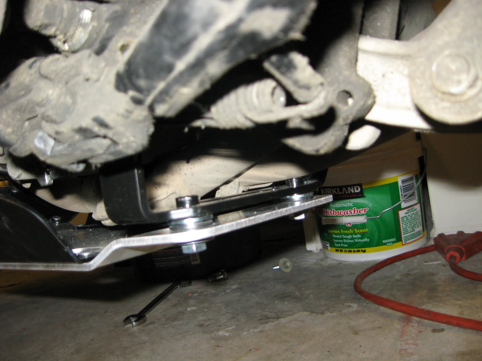
Now, take the two last bolts and the two last washers, and fit them through the rubber grommets and metal washer-things at the rear of the skidplate. Again, I used a little blue Locktite to keep the bolts from working loose while riding. If you need to adjust the positioning, you can rotate the crash bar clamp to move the skidplate forwards or backwards so that the rear bolts line up with the bracket. Then, once everything you've got everything lined up, tighten up the two rear bolts and the two front bolts.

Here's the completed install.


A couple of comments about the skidplate, now that I've got it installed: on the plus side, it looks very sturdy and very robust. I wish the Wee had a little more ground clearance, but the skidplate should help minimize the problems with clearance, since I would have to hit a rock or a stump pretty hard to damage the oil cooler or exhaust headers with the skidplate installed. On the negative side, SW-Moetch seems to have left a lot of empty space under the oil filter, oil pan and front of the headers, which only makes the ground clearance worse. The plumbing for the exhaust pipe sits a little lower than I expected where the rear cylinder headers join with the forward cylinder headers, and the skidplate has to be even lower than that. I suspect SW-Motech wanted to keep the skidplate as smooth as possible to allow the bike to slide over rocks, stumps and/or logs, but I still wish the front of the skidplate was fit a little closer to the engine. I guess you can always use the extra space to carry tools or water though!

Electrical System Upgrades, Part 3

This section could also be titled, "Will I Ever Get To, You Know, RIDE This Motorcycle Again?!?!" I've been working on the Wee for over a month, now. The gas tank is sitting in a corner of my garage. The fairing trim pieces, mounting hardware and other assorted odd ends are sitting on a small table in the garage that my daughter no longer has room for in her bedroom. Tools are scattered everywhere, and the Wee looks naked with the gas tank, trim and seat removed.

Fortunately, there is a light at the end of the tunnel. After a month of work, almost everything is wired up. I've got both the +12V and ground terminal strips installed, the main electrical accessories relay is installed and connected, the fog light relay is installed and connected to the Autoswitch (Note: looks like Aerostich no longer sells the model I bought; the link goes to the new version of the switch) and the fog lights are connected to both the relay (for power) and to ground. The only step left is installing the Autoswitch indicator light and connecting the trigger wire.

Here's a photo of the Autoswitch, just behind the battery. Route the wires to the positive voltage source (the +12V terminal strip, in my installation), to ground, to the high-beam power lead, and route the LED indicator to the fairing.

In this photo, I am wrapping the Autoswitch trigger wire and the indicator wires to the OEM wire bundle with spiral wrap.

The trigger wire has to be connected to the high-beam power lead. However, there are three wires going to the headlights/high-beam lights on the DL650. To find out which wire I needed to tap into, I disconnected the connector from the light bulbs and used a multimeter to find the ground wire (it was the black wire with the white stripe). Then, I turned the ignition key to the on position and used the multimeter to find which of the remaining wires had power at all times (the yellow wire) and when the high-beam switch was in the "on" position (the solid black wire). The solid black wire, then, was the wire that I attached the vampire tap to.

After getting the trigger wire hooked up, and installing the indicator LED in the fairing, I reinstalled the gas tank, re-attached the front fairings and, for the first time in over a month, heard that sweet, sweet V-Twin sound again :) Okay...the bike still runs. Good! Do the heated grips work? Yep! All right...if I'm really, really careful with the multimeter, I should see 12V from the accessory outlet...yep, that works. Woohoo! So far, so good. Does the Autoswitch turn on my fog lights?

@$#^$^#%&*@!!!!!!!!!

Nope. I trigger the high-beam switch for one second, but I don't get the indication that it's turning on power to the fog lights, and the fog lights are dark. Nuts...I knew things were going too well! Either I wired something up incorrectly, the Autoswitch is defective or riding last summer with fog lights hung from my crash bars broke the filaments in the bulbs. I've got LEDs coming in the mail to replace the halogen fog light bulbs; they should be here today (Edit: they arrived, I have installed them; see the review here). I'll connect them before I start ripping wiring apart, in the hopes that it's just bad bulbs.

Here's a shot of the installed SW-Motech 12V accessory outlet (and the SW-Motech flush mount mounting bracket).

Still to come: troubleshooting the fog lights, replacing the worn OEM Bridgestone Trailwing Tire with a Shinko 705 and installing the SW-Motech skid plate...after I change the oil and coolant.

EDIT: The fog lights work fine; the Autoswitch just doesn't work the way I thought it did. First, hitting the button to flash the high-beams won't trigger the Autoswitch. I don't understand why -- it would seem to me that if the high-beam bulb gets electricity, that should be sufficient to trigger the Autoswitch -- but okay, whatever. Second, the Autoswitch instructions state that you turn on the high-beams for one second, then turn them off to turn on the fog lights. Huh-uh. That doesn't work. Rock the high-beam switch on and then off. When you do that, you will see the LED start flashing. Now rock the high-beam switch on and then off again. That will turn on the fog lights. Do the same thing to turn the fog lights off again. I'm not sure why it doesn't work the way the instructions say it should, but at least it works. I'm happy :)

Wednesday, March 28, 2012

Inspirational Photography for ADV Motorcyclists

I found the following photography blog post while dreaming of warmer temperatures and no more snow the other day: Reuters.com: Dreaming of the Dakar Rally. If the photos on that blog don't make you want to sell your house, quit your job and ride around the world, then you may as well check yourself into the morgue, 'cause you no longer have a heart :) Enjoy!

Thursday, March 15, 2012

Wiring Up the Gadgets

In my last post, I discussed some of the new goodies I was installing on my motorcycle. However, I pretty much avoided the topic of the electrical work necessary to get some of the devices working. In particular, heated grips and a 12V power outlet don't do much good if they aren't connected to the bike's electrical system. Here's how I did it.

First, I decided to install terminal strips so that it would be relatively easy to install new devices. I purchased an assortment of terminal strips, from 4-12 connections per strip. Unfortunately, there's not a lot of space around the engine, so I ended up using the 4-outlet terminal strips -- one for the positive bus (shown) and one for the ground bus. The next question is where to install the busses? I noticed that there is quite a lot of space behind the rear quarter panels, so that is where I decided to install the positive bus, the extra wiring and the heat controller circuitry. Pulling the left-hand, rear panel is pretty straightforward, although it required removing the SW-Motech side cases and the OEM rear luggage rack. Once the body panel was removed, I found a suitable location to mount the terminal strip. There is a cross-brace on the frame that is already drilled with two holes. Unfortunately, they are too large diameter and too far apart to hold my terminal strip, so I had to drill two 1/8 inch holes, then I pop-riveted the terminal strip to the frame.

Next, I had to find a place to mount the relay that turns on 12V power to the positive bus. I picked up a Bosch 40A automotive relay at the local electronics parts dealer and a wiring harness for the relay. Again, in hindsight, the wiring harness may not have been a great idea; it doubles the size of the relay and I still have to crimp connectors to the wires whereas I could have simply crimped a blade connector to the wiring and kept the size a little smaller. However, near the rear of the frame, there is a plastic fender that separates the battery and storage compartment from the wheel well. I drilled a 1/8 inch hold in the fender, smeared some liquid electrical tape (basically, a rubberized glue) on both the inside and outside of the fender, and pop riveted the relay to the fender.

Route the wires from the heated grips and 12V outlet around the triple clamps...

...under the frame and alongside the existing wire bundles between the frame and the engine. To keep things neat and to protect the wires, I wrapped them in spiral wrap.

Connect the positive lead TO the terminal strip to the battery, then route it under the frame to the terminal strip. Again, to keep things neat and to protect the wire, I wrapped it in spiral wrap.

To be continued...

Thursday, March 8, 2012

Finally Installing Heated Grips Among Other Odds and Ends

Last winter, I wrote about some intended electrical upgrades. Summer arrived before I had the opportunity to install the fog lights or the terminal strips for future electrical upgrades. So, I'm revisiting that project this year. Also, my wonderful, sweet, loving wife bought me a set of Oxfords Heated Grips for Christmas (thank you, honey!) and I am installing them, too. Here's how you do it.

First, remove the bar end weights from the handlebars. Don't pull the screw all the way out -- just loosen it up. Inside the handlebars, there are a series of washers, spacers and rubber bushings. The screw pulls on the rubber bushings, causing them to expand and press against the handlebars, holding them in place. If you pull the screw out of the bar end weights, the bushings will get stuck in the handlebars. It's possible to get it out, but it's not any fun (ask me how I know...).

Here's the entire bar end weight assembly after being removed from the handlebar.

Next, you have to remove the stock grips. This was arguably the hardest part for me. It's not physically difficult to do; I just couldn't bring myself to cut the grips. I found out later that you can use compressed air to blow the grips off. Wish I'd read that before cutting my grips off :rolleyes:

The left side is pretty straightforward. Use some sandpaper to remove the contact cement from the handlebars after removing the grip. The throttle side, however, is a bit more difficult. The Oxfords grips are really stiff, and need the throttle tube to be perfectly smooth. Unfortunately, Suzuki created the throttle tube with flanges at each end to help hold the grip on the throttle tube...

...and ridges along the length of the throttle tube to keep the grip from slipping when you grab a fistful of throttle (not that you or I would ever do anything like that!)

To solve this problem, grab a file and get to work on those ridges and flanges. After getting them reasonably smooth, use some sandpaper to finish the job. Oxfords recommends checking the inside of the grips for flash from the manufacturing process. My right hand grip had some flash in it, but the left side was okay. While I'm not terribly impressed that Oxfords couldn't clean up their grips before shipping them out, it's easy enough to do yourself with a small file. It took me all of maybe two minutes to do.

Before installing the grips, it is critically important to spend a while finding the best mounting orientation. You don't want the power wires to foul your brake, clutch or fairing, so spend a couple of minutes trying different positions on the throttle tube and handlebar. Make sure you take the time to verify that you still have clearance while rotating the throttle. You *DON'T* want to find out that your brake doesn't clear the power wires at highway speeds!

Once you are satisfied with the positioning, use the included high-temp super glue (!) to glue the grips in place. If anyone at Oxfords happens to stumble across this page, super glue, IMHO, is an exceptionally poor choice since you do not get nearly enough time to position the grips before the glue sets. Seriously, was there *nothing* that you could find that was flexible enough and heat resistant enough (high temp silicone, maybe?) for this purpose? </rant> Anyway, back to the install. First, coat the inside of the grip -- NOT the handlebar!!! -- with super glue, then QUICKLY slide the grips on the handlebar or throttle tube. You have to work fast! This stuff sets very, very quickly, and once it grabs, you are DONE. Again, ask me how I know (sigh)


Congratulations! The hard part is done. Now, it is time to install the heat controller. Oxfords had an ingenious solutions for affixing the controller to the somewhat crowded real estate on a motorcycle's handlebars: mount the controller on a metal bracket that is drilled to match the mounting holes on the left-hand rear view mirror on some motorcycles. Simple, right?

Unfortunatley, on V-Stroms -- or at least on my K9 DL650 -- there's a snag. The left-hand rear view mirror mount only has one bolt, but the Oxford bracket requires an upper and lower mounting bolt. It would match the bolts on the right-hand side mount, but the metal bracket is cut to fit on the left hand side only, and honestly, I wouldn't want to let go with my throttle hand to change heat settings anyway. I was able to work around the problem by buying a conduit clamp at Lowe's and mounting the bracket to it. It took a little work with some pliers to match the holes in the clamp to the holes in the bracket, but I finally got them to mate up. Then, I wrapped the clamp in electrical tape (so the metal clamp wouldn't abrade the handlebars), and bolted the bracket to the clamp.

Here's the completed install:


One other problem I ran into: the diagram doesn't show it, but there should be an adhesive pad between the controller and the metal bracket. The bracket and controller are held together by two screws, but the pad acts as a shock absorber so that vibrations in the handlebars don't get transmitted to the electronics in the controller. Of course, I didn't see that until after I had already screwed the controller onto the bracket, requiring me to remove the screws, remove the controller, install the adhesive pad, then reinstall the screws. It's not a big deal, but by this point, the frustration level was mounting.

The only thing left to do at this point is the electrical wiring. However, I'm still working on several facets of that project, so..."To be continued" :)

Saturday, March 3, 2012

Brake Maintenance

Winter is a good time to take care of all those maintenance chores that you put off during riding season. I'm currently working on a number of upgrades and modifications to my V-Strom while there's still a couple of feet of snow outside, so an e-mail I received today was very timely ;) I don't quite think it's time to replace brake pads and/or rotors yet, but my bike is three years old, so it's probably time to think about replacing the brake fluid. Fortunately, the guys at Bike Bandit wrote up a pretty thorough tutorial on brake maintenance. I am posting the link here for anyone reading my blog (and also for me to refer to when I need to work on MY brakes!).


For those of you wondering, I have no affiliation with Bike Bandit other than being a happy customer. I've bought a few items from them, and they've treated me fairly (although I wish they would ship tires to Alaska!). They don't pay me to link to their site, nor do I receive any referrals back from them.